A loopback interface is a virtual interface in our network device that is always up and active after it has been configured. Like our physical interface, we assign a special IP address which is called a loopback address or loopback IP address.
Loopback interfaces should be supported on all Cisco platforms, and unlike subinterfaces, loopback interfaces are independent of the state of any physical interface. Most IP implementations support a loopback interface (lo0) to represent the loopback facility. Any traffic that a computer program sends on the loopback network is addressed to the same computer.
The loopback interface can be considered stable because once you enable it, it will remain up until you issue the shutdown command under its interface configuration mode. It’s very useful when you want a single IP address as a reference that is independent of the status of any physical interfaces in the networking device.
Loopback addresses are not limited to the 127.0.0.0/8 block.
Benefits of Having a Loopback Address
We would reap the following advantages and benefits of having loopback interfaces and loopback addresses in our network:
- A good example is mapping a router’s loopback IP address to its DNS server address.
- You can also configure the loopback address as the Router ID for routing protocols like OSPF and BGP.
- A loopback interface can also be used to establish a Telnet session from the console port of the device to its auxiliary port when all other interfaces are down.
- TACACS+ or RADIUS can use the loopback address as a source address for AAA functions and thereby reducing the administration overhead of having to add every IP address of the router to the AAA server.
- It is also recommended that the unnumbered interface points to a loopback interface since loopbacks do not fail. The ‘ip unnumbered’ configuration command allows you to enable IP processing on a serial interface without assigning it an explicit IP address.
- Loopback address becomes even more important in large fully meshed or route-reflector BGP environments where many routers will have multiple peering with many other BGP speakers. Adding and troubleshooting other services like LDP for MPLS or building MPLS L2 cross-connects, loopback address becomes extremely important to easily identify the peer routers to deliver the services in large Service Provider environments.
- It can also be used as a source and destination address for testing network connectivity and lab environments.
- It also allows us to test IP software without worrying about broken or corrupted drivers or hardware.
Loopback Configuration
I am going to show you how to configure the loopback interface and loopback address and use it as the Router ID for OSPF. We’ll use the network topology below for the sample configuration. Let’s start by configuring the physical and loopback interfaces.
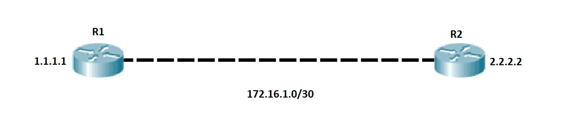
R1
R1#conf t
R1(config)#int gigabitEthernet 0/0
R1(config-if)#ip add 172.16.1.1 255.255.255.252
R1(config-if)#no shut
R1(config-if)#int lo0
R1(config-if)#ip address 1.1.1.1 255.255.255.255
R2
R2#conf t
R2(config)#interface gigabitEthernet 0/0
R2(config-if)#ip address 172.16.1.2 255.255.255.252
R2(config-if)#no shut
R2(config-if)#int lo0
R2(config-if)#ip address 2.2.2.2 255.255.255.255
Then, we configure OSPF.
R1
R1#conf t
R1(config)#router ospf 1
R1(config-router)#network 1.1.1.1 0.0.0.0 area 0
R1(config-router)#network 172.16.1.0 0.0.0.255 area 0
R2
R2#conf t
R2(config)#router ospf 1
R2(config-router)#network 2.2.2.2 0.0.0.0 area 0
R2(config-router)#network 172.16.1.0 0.0.0.255 area 0
Next, it’s time to verify. We can now see that the OSPF neighborship is established.
R1#sh ip ospf neighbor

Neighbor ID     Pri   State           Dead Time   Address         Interface
2.2.2.2           1   FULL/BDR        00:00:35    172.16.1.2      GigabitEthernet0/0
R2#sh ip ospf neighbor

Neighbor ID     Pri   State           Dead Time   Address         Interface
1.1.1.1           1   FULL/DR         00:00:34    172.16.1.1      GigabitEthernet0/0
Let’s ping the loopback IP address from both R1 and R2.
R1# ping 2.2.2.2
Type escape sequence to abort.
Sending 5, 100-byte ICMP Echos to 2.2.2.2, timeout is 2 seconds:
!!!!!
Success rate is 100 percent (5/5), round-trip min/avg/max = 2/3/4 ms
R2#ping 1.1.1.1
Type escape sequence to abort.
Sending 5, 100-byte ICMP Echos to 1.1.1.1, timeout is 2 seconds:
!!!!!
Success rate is 100 percent (5/5), round-trip min/avg/max = 2/2/3 ms
If there is no OSPF Router ID configured, the highest loopback IP address is selected as the OSPF Router ID.
R1#sh ip protocols
*** IP Routing is NSF aware ***

Routing Protocol is "application"
  Sending updates every 0 seconds
  Invalid after 0 seconds, hold down 0, flushed after 0
  Outgoing update filter list for all interfaces is not set
  Incoming update filter list for all interfaces is not set
  Maximum path: 32
  Routing for Networks:
  Routing Information Sources:
    Gateway         Distance      Last Update
  Distance: (default is 4)

Routing Protocol is "ospf 1"
  Outgoing update filter list for all interfaces is not set
  Incoming update filter list for all interfaces is not set
  Router ID 1.1.1.1
  Number of areas in this router is 1. 1 normal 0 stub 0 nssa
  Maximum path: 4
  Routing for Networks:
    1.1.1.1 0.0.0.0 area 0
    172.16.1.0 0.0.0.255 area 0
  Routing Information Sources:
    Gateway         Distance      Last Update
    2.2.2.2              110      00:02:49
  Distance: (default is 110)
Download our Free CCNA Study Guide PDF for complete notes on all the CCNA 200-301 exam topics in one book.
We recommend the Cisco CCNA Gold Bootcamp as your main CCNA training course. It’s the highest rated Cisco course online with an average rating of 4.8 from over 30,000 public reviews and is the gold standard in CCNA training: