The latest Cisco Catalyst Switches are equipped with the Enhanced Multilayer Image (EMI), which can work as a Layer 3 device with full routing capabilities, also known as a multi-layer switch (MLS). Below are some of the Cisco Catalyst Series switches with Layer 3 functionalities:
- Cisco Catalyst 3560
- Cisco Catalyst 3570
- Cisco Catalyst 4500/4000 Series with Sup II+ or later
- Cisco Catalyst 6500/6000 Series
A Layer 3 Switch can route from one VLAN to another using multiple Switched Virtual Interface (SVI). Layer 3 switches convert a Layer 2 switch interface to a Layer 3 interface, making it a routed port similar to a physical interface on a Cisco IOS router.
How to Configure Layer 3 Switch InterVLAN Routing?
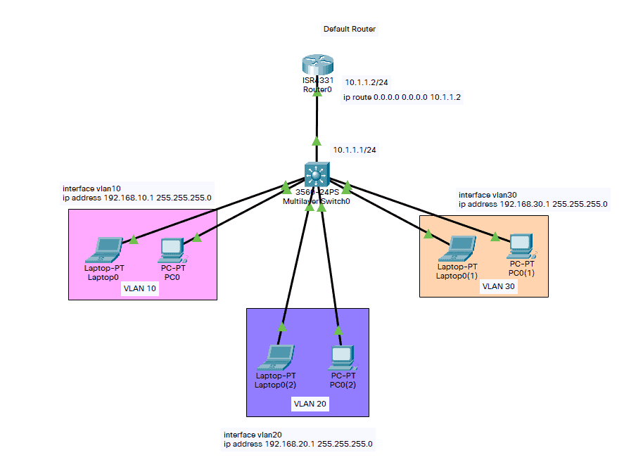
Below is a diagram that we can use as a reference in understanding how to configure Inter-VLAN routing and test inter-switch connectivity across the network before configuring its routing capability. In this simple Inter-VLAN routing scenario, we will be using a Cisco Catalyst 3550 as our Layer 3 Switch.
Step 1: Enable routing capability on the switch. Even though this command is usually enabled, it does not hurt to be certain that it is.
Switch(config)#ip routing
Step 2: Take note of the VLANs that must be routed. Based on the network topology above, it is VLANs 10, VLAN 20, and VLAN 30.
Step 3: Use the ‘show vlan’ command to verify that the VLANs exist in the VLAN database. If they do not exist, add the VLANs to the switch. This example shows the addition of VLANs 2, 3, and 10 to the switch VLAN database.
Switch#vlan database
Switch(vlan)#vlan 10
VLAN 10 added:
    Name: VLAN0010
Switch(vlan)#vlan 20
VLAN 20 added:
    Name: VLAN0020
Switch(vlan)#vlan 30
VLAN 30 added:
    Name: VLAN0030
Switch(vlan)#exit
APPLY completed.
Exiting....
Step 4: Configure the IP address on the VLAN interfaces based on the network diagram above.
Switch#configure terminal
Enter configuration commands, one per line.  End with CNTL/Z.
Switch(config)#interface Vlan10
%LINK-5-CHANGED: Interface Vlan10, changed state to up
Switch(config-if)#ip address 192.168.10.1 255.255.255.0
Switch(config-if)#no shutdown
Switch(config-if)#interface Vlan20
%LINK-5-CHANGED: Interface Vlan20, changed state to up
Switch(config-if)#ip address 192.168.20.1 255.255.255.0
Switch(config-if)#no shutdown
Switch(config-if)#interface Vlan30
%LINK-5-CHANGED: Interface Vlan30, changed state to up
Switch(config-if)#ip address 192.168.30.1 255.255.255.0
Switch(config-if)#no shutdown
Step 5: IP configuration facing the default router should look like the commands below. In this case, it is FastEthernet 0/1 for the Cisco Catalyst 3550.
Switch(config)#interface FastEthernet 0/1
Switch(config-if)#no switchport
Switch(config-if)#ip address 10.1.1.1 255.255.255.0
Switch(config-if)#no shutdown
The ‘no switchport’ command allows the physical ports to attain Layer 3 routing functionality. The IP address allocated is within the same subnet as the default router.
This step can be disregarded if the switch reaches the default router through a VLAN. In its place, configure an IP address for that VLAN interface.
Step 6: Configure the default route for the switch.
Switch(config)#ip route 0.0.0.0 0.0.0.0 10.1.1.2
Layer 3 Switch InterVLAN Verification
We can use the following show commands to confirm that our Layer 3 Switch interVLAN configuration runs properly:
- show ip route – provides a snapshot of the routing table entries.
Switch#show ip route
Codes: C - connected, S - static, I - IGRP, R - RIP, M - mobile, B - BGP
       D - EIGRP, EX - EIGRP external, O - OSPF, IA - OSPF inter area
       N1 - OSPF NSSA external type 1, N2 - OSPF NSSA external type 2
       E1 - OSPF external type 1, E2 - OSPF external type 2,
       i - IS-IS, su - IS-IS summary, L1 - IS-IS level-1, L2 - IS-IS level-2,
       ia - IS-IS inter area, * - candidate default, U - per-user static route,
       o - ODR, P - periodic downloaded static route

Gateway of last resort is 10.1.1.2 to network 0.0.0.0

     10.1.1.0/30 is subnetted, 1 subnets
C       10.1.1.0 is directly connected, GigabitEthernet 0/0/0
     192.0.0.0/24 is subnetted, 3 subnets
C       192.168.10.0 is directly connected, Vlan10
C       192.168.20.0 directly connected, Vlan20
C       192.168.30.0 is directly connected, Vlan30
S*   0.0.0.0/0 [1/0] via 10.1.1.2
The routing table has an entry for each VLAN interface subnet. Therefore, devices in VLAN 30 can communicate with devices in VLAN 10, VLAN 20, and vice versa. The default route with the next hop 10.1.1.2 allows the switch to forward traffic to the gateway of last resort (for traffic the switch cannot route).
- show ip interface brief – lists a brief summary of an interface’s IP information and status. This command is used to verify that the VLAN interfaces and ports on the switch are up/up.
Download our Free CCNA Study Guide PDF for complete notes on all the CCNA 200-301 exam topics in one book.
We recommend the Cisco CCNA Gold Bootcamp as your main CCNA training course. It’s the highest rated Cisco course online with an average rating of 4.8 from over 30,000 public reviews and is the gold standard in CCNA training: