The organization uses redundancy to protect its network from sudden service interruption due to the unavailability of the default gateway router. To optimize the usage of gateway redundancy such as Hot Standby Router Protocol (HSRP), we need to align its operation to network switches Spanning Tree Protocol (STP).
HSRP and STP Alignment Explained
To optimize our network redundancy, we need to design our network that aligns both Cisco Layer 3 HSRP and Layer 2 STP redundancy services with each other. By default, STP is enabled on most interconnected Cisco switches. It assigns a root bridge within the interconnected switches. A root bridge is the central point of all switches and will be responsible for forwarding the traffic.
HSRP, on the other hand, will assign the active and the standby router based on priority. The highest priority will be the active HSRP router amongst the HSRP group. All the routers within the cluster will have the same virtual IP address and virtual mac address. It has two states active and standby routers. If the active HSRP router fails, the local standby router will be the new active router. The standby IP address and active IP address will be the same for all routers within the HSRP group. The local virtual MAC address is also the same and is automatically generated by the router. HSRP’s virtual MAC address is 0000.0c07.acXX, where XX is the HSRP group number.
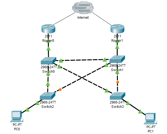
Looking at the example network diagram above, let’s assume that Router0 is the active router in the network and Switch0 is the root bridge, then the traffic from PC0 will go to Switch2 > Switch0 > Router0, while the traffic from PC1 will go to Switch3 > Switch0 > Router0. What if Router0, the active router, fails and goes offline, and the new active router will be Router1? The traffic path will be different now. The traffic from PC0 will now go to Switch2 > Switch0 > Switch1 > Router1 and the traffic from PC1 will now go to Switch3 > Switch0 > Switch1 > Router1.
That traffic route during failover is not an efficient way to route the traffic. To solve this, we need to align the HSRP and the STP configurations. We need to tag a different VLAN on each of the access switches, Switch2 and Switch3.
Cisco HSRP and STP Alignment Configuration
To better understand the concept, let’s have an example using the topology below. Please follow the below steps on HSRP and STP configuration:
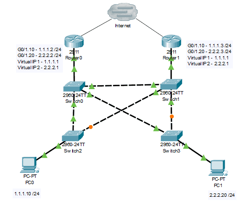
1. Add the following commands to Router0. We will configure HSRP and add the virtual standby IP address.
Router#conf t

Router0(config)#interface gigabitEthernet 0/1

Router0(config-if)#no shutdown

Router0(config)#interface g0/1.10

Router0(config-subif)#encapsulation dot1Q 10

Router0(config-subif)#ip address 1.1.1.2 255.255.255.0

Router0(config-subif)#no shutdown

Router0(config-subif)#standby 1 ip 1.1.1.1

Router0(config-subif)#standby 1 priority 110

Router0(config-subif)#standby 1 preempt
Router0(config)#interface gigabitEthernet 0/1.20

Router0(config-subif)#encapsulation dot1Q 20

Router0(config-subif)#ip address 2.2.2.2 255.255.255.0

Router0(config-subif)#no shutdown

Router0(config-subif)#standby 2 ip 2.2.2.1

Router0(config-subif)#standby 2 priority 90
2. Add the following commands to Router1. We will configure HSRP and the virtual IP address.
Router1#conf t

Router1(config)#interface gigabitEthernet 0/1

Router1(config-if)#no shutdown

Router1(config)#interface g0/1.10

Router1(config-subif)#encapsulation dot1Q 10

Router1(config-subif)#ip address 1.1.1.3 255.255.255.0

Router1(config-subif)#no shutdown

Router1(config-subif)#standby 1 ip 1.1.1.1

Router1(config-subif)#standby 1 priority 90
Router1(config)#interface gigabitEthernet 0/1.20

Router1(config-subif)#encapsulation dot1Q 20

Router1(config-subif)#ip address 2.2.2.3 255.255.255.0

Router1(config-subif)#no shutdown

Router1(config-subif)#standby 2 ip 2.2.2.1

Router1(config-subif)#standby 2 priority 110

Router1(config-subif)#standby 2 preempt
3. Add the following commands to Switch0:
Switch0#conf t

Switch0(config)#spanning-tree vlan 10 root primary

Switch0(config)#spanning-tree vlan 20 root secondary
4. Add the following commands to Switch1:
Switch1#conf t

Switch1(config)#spanning-tree vlan 10 root secondary

Switch1(config)#spanning-tree vlan 20 root primary
5. The following are the show commands to verify our configuration.
For Router0 and Router1:
Router#show standby
For Switch0 and Switch1:
Switch#show spanning-tree vlan <vlan #>
Download our Free CCNA Study Guide PDF for complete notes on all the CCNA 200-301 exam topics in one book.
We recommend the Cisco CCNA Gold Bootcamp as your main CCNA training course. It’s the highest rated Cisco course online with an average rating of 4.8 from over 30,000 public reviews and is the gold standard in CCNA training: